Graticule Design (UK) ~ Reticle Design (USA)
CADtec3D has many years' experience designing bespoke Graticule (Reticle) patterns for all calibres.
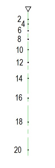
This can range from relatively simplistic patterns for rifle scopes of a single calibre or Turret systems with multiple calibres.
Sample simplistic pattern shown below:
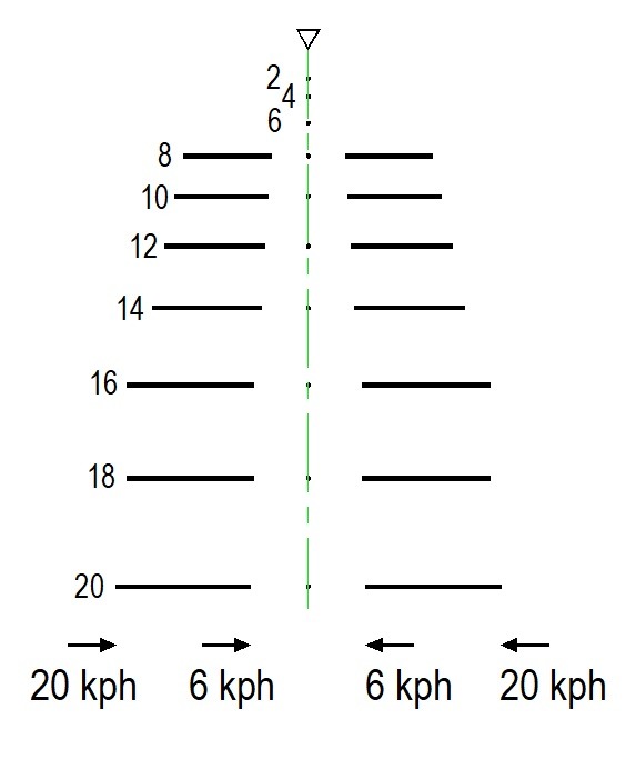
We can add "aim off" indicators for moving targets for 2 specific speeds. Can be more or less dependent on your requirement!
See sample below:
We can add "range indicators (using stadia lines) to estimate range". Simply apply a "best fit" and read off the distance from the chart.
The sample below indicates an estimated distance of 400 Meters
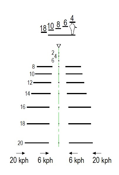
Please note that all the aiming marks for all the ranges above are all on the "plum verticle" centre line!
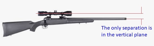
That is because they are typically for rifle scopes where the scope is directly above the barrel and therefore suffer from negligible parallax error in the vertical plan and zero parallax error in the horizontal plane.
All things being equal, the only errors in the horizontal plane come from badly estimated range, windage and round drift for example.
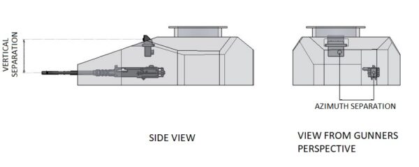
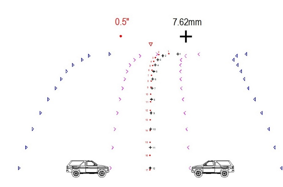
When it comes to Turret systems where the Sight and Weapons are offset in both planes, everything changes!
The images below shows exactly this situation.
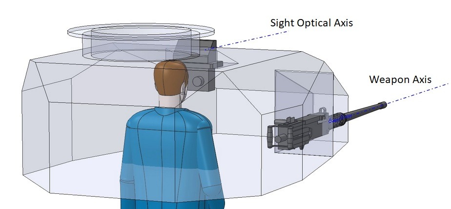

Separations of 1 meter in the azimuth plane and 0.4 meter in the vertical plane is very possible.
Parallax of this type will cause huge errors down range if not corrected on the Graticule, especially at close range.
The pattern below has been corrected for parallax. The tell tale-sign is the "walking stick handle" shape at close ranges and you will note the 800 meters range is on the plum line because this example was bore sighted at 800 metres (no theoretical error then at this range. Gun Sight Optical axis and Barrel axis are coincident at boresight distance!
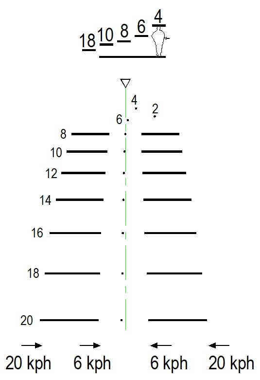
But you are NOT ONLY going to fire at 800 meters! So what happens when you fire at ranges closer and further than the boresight range?
Ranges further than the boresight distance will see fall of shot in azimuth go LEFT
Ranges further than the boresight distance will see fall of shot in the vertical plane go HIGH
Ranges closer than the boresight distance will see fall of shot in azimuth go RIGHT
Ranges closer than the boresight distance will see fall of shot in the vertical plane go LOW.
If you look at the pattern above you will notice ranges beyond 800 meters are gradually moving to the left of plum, ranges closer than 800 meters are gradually moving to the right of plum.
The boresight distance and the sight / weapon separation form an angular relationship that is constant.
That is why and how it is capable of calculating the errors that occur at closer and further ranges due to the "cross-over" effect.
Graticule ~ Reticle pattern design services page divider
In order to design the most accurate Graticule Pattern we will need to know the following information:
# Super Elevation for each range
# Time of flight for each range
# Round drift (if known)
# The above information can be obtained from the supplier of the rounds known as range tables.
It may be that you have your own measured data that takes into effect characteristics of the overal weapon system like barrel jump / barrel cradle whip etc. This will be an improvement on the accuracy of the pattern.
We would need to know your preferred boresight distance!
We would need to know your intended ranges as seen on the graticule pattern!
We would need to know the spatial layout of your turret with respect to the position of weapon/s in relation to the gun sight optical path, i.e. please supply these dimensions below from the gunners perspective.
Lastly, we will need to know the optical data of your gun sight:
# Focal length of the OG
# Focal length of the eye piece
Graticule ~ Reticle pattern design services page divider
We like to ensure line thicknesses are not too heavy in order to maximise the field of view through the Graticule disc, but not too small as to make seeing them too difficult. We use a resolution that equates to reading 1.6mm high text at 250mm distance. We can supply you with a scaled print of the pattern which we advise you to view at a specific distance so as to simulate exactly what you will be seeing through the eye piece.
The reason we require the OG focal length is to convert angular measurements to actual linear dimensions on the Graticule disc. We compute all the superelevation angles for all the ranges including round drift if known, then make further adjustments of the aiming marks taking the parallax errors into account for all the ranges further and closer than the boresight range in both the azimuth and vertical planes.
The reason we require the Eye Piece focal length is to determine the resolution of the line thicknesses as viewed through the eye piece.
The reason we need the Ballistic data of the rounds you intend to use and the spatial relationship of the Sight and Weapon/s system is to calculate the position of the aiming marks allowing for Super elevation, Round Drift (if known), Parallax and any other characteristic you may know about your own system.
The reason we need to know the boresight distance is that there must be a consistent angular relationship between the sight optic axis and the weapons in order to calculate the ballistic and mechanical parallax errors. Once the bore sight distance is agreed it must be adhered to else the Graticule pattern will have errors.
Graticule ~ Reticle pattern design services page divider
Below is a sample Graticule that has multiple aiming marks for 2 weapon systems and aim offs for 2 different speeds
Please remember, if you are looking for 1st hit capability and not relying on observation of fall of shot and correcting, you absolutely need to ensure your aiming system is corrected for parallax!
"Bullet drop" or "effects of gravity" are not your enemy! Parallax is!
By way of example, a 50 calibre has a relatively flat trajectory; Super elevation for 100 meter’s = 0.116 degrees, that equates to a 66mm drop in 100 yards in the vertical plane. However, in this example where the Turret setup is:
As viewed by the gunner:
Weapon is 250mm lower than the sight optic axis
Weapon is 600mm to the right of the optic axis
At 100 meters in the vertical plane, the combined error of gravity and parallax is 225mm (fall is low)
At 100 meters in the horizontal plane, the combined error is 540mm (fall is right of plum from the MBS (muzzle bore sight mark)
Turret boresight distance = 1000 meters.
If this Graticule was used on a rifle scope where the optics were situated vertical and adjacent to the barrel, error at 100 meters would be:
Vertical plane = 65mm low
Horizontal plane = 0mm (no theoretical error)
Graticule ~ Reticle pattern design services page divider
If you have a requirement for a custom Graticule please contact us on an absolutely free and no commitment initial consultation using any method at the top of the page.
Graticule Reticle Design - by Brian Grice IEng MIMechE